Exploring the Dynamic Response of Capacitors to AC and DC Signals
Capacitors are fundamental components in electronic circuits, widely used for energy storage, filtering, and coupling applications. Understanding how capacitors respond to alternating current (AC) and direct current (DC) signals is crucial for designing and troubleshooting electronic systems. In this article, we will delve into the intricate behavior of capacitors in both AC and DC circuits, exploring their response characteristics and practical implications.
- Capacitor Basics:
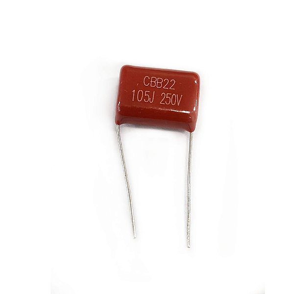
Before we delve into the response of capacitors to AC and DC signals, let's briefly review the fundamental principles. A capacitor consists of two conductive plates separated by an insulating material, known as a dielectric. When a voltage is applied across the plates, an electric field is established, causing the accumulation of charge on each plate. The amount of charge stored is directly proportional to the voltage applied and the capacitance of the capacitor. - Capacitor Response to DC Signals:
In a DC circuit, where a constant voltage is applied, capacitors act as open circuits once they are fully charged. Initially, when the voltage is applied, the capacitor charges up exponentially until it reaches its maximum charge, following the equation Q = CV, where Q is the charge, C is the capacitance, and V is the voltage. Once fully charged, the capacitor blocks the flow of DC current, behaving as an open circuit. - Capacitor Response to AC Signals:
In an AC circuit, where the voltage varies sinusoidally over time, capacitors exhibit a dynamic response due to their ability to store and release charge. The behavior of capacitors in AC circuits can be understood through two key concepts: capacitive reactance and phase shift.
- Capacitive Reactance: Capacitors oppose the flow of AC current, offering a reactance known as capacitive reactance (Xc). The capacitive reactance is inversely proportional to the frequency of the AC signal and the capacitance of the capacitor, following the equation Xc = 1 / (2πfC), where f is the frequency. As the frequency increases, the capacitive reactance decreases, allowing more current to flow through the capacitor.
- Phase Shift: When an AC signal is applied to a capacitor, the voltage across the capacitor lags behind the current flowing through it. This phase shift occurs because the capacitor takes time to charge and discharge. The phase shift angle (φ) between the voltage and current can be calculated using the equation φ = arctan(Xc/R), where R is the resistance in the circuit. The phase shift can have significant implications in AC circuits, affecting the overall power factor and circuit behavior.
- Practical Applications:
Understanding how capacitors respond to AC and DC signals is essential for various practical applications. Some notable applications include:
- Filtering: Capacitors are commonly used in AC circuits to filter out unwanted frequencies, allowing only specific frequencies to pass through. By selecting the appropriate capacitance and reactance, capacitors can effectively attenuate noise and improve signal quality.
- Coupling: Capacitors are used for coupling signals between different stages of amplifiers or electronic circuits. They allow the AC component of the signal to pass while blocking the DC component, ensuring proper signal transmission without interference.
- Energy Storage: Capacitors store electrical energy and can be used to provide short bursts of power in applications such as camera flashes, motor starting, and power backup systems.
Conclusion:
Capacitors exhibit unique responses to AC and DC signals, making them versatile components in electronic circuits. Their ability to store and release charge, along with their reactance and phase shift characteristics, allows for various applications in filtering, coupling, and energy storage. By understanding the dynamic behavior of capacitors, engineers and designers can optimize circuit performance and ensure reliable operation in diverse electronic systems.